Frame structure with Numerologies
10 subframes (= 20 slots) are fit into 10 ms in LTE while various number of slots depending on Numerology are fit into 10 ms in 5G NR. Yes it brought multiple options in sub-carrier spacing, which is called as Numerologies; 15 through 240 kHz. Let me illustrate New Radio frame structures with multiple SCS below.

It is hard to see this type of illustration because there are multiple sub-carrier spacing and it is barely provided as a picture. I was able to draw this above as putting pieces together; TS 38.211 Table 4.2-1 and Table 4.3.2-1. Both table would be combined into one with my understanding here.

For your reference, let's compare the LTE frame and 5G NR's with 15 kHz. As long as you would see both subframe and slot at the same time, you would get confused. LTE resource would be allocated every subframe base while NR's would be done every slot base.

Slot configuration with Numerologies
As you can see, 14 symbols would be stuffed in a single subframe (= 2 slots = 1 ms) in LTE while the same number of symbols would be fit into a single slot (= 1 subframe = 1 ms) in NR with 15 kHz SCS. In LTE, 14 symbols would be fit into a single subframe, which is always 1 ms. In NR, 14 symbols would be done into a single slot, which varies per subcarrier spacing. Since the absolute slot size (length) are defined differently as SCS, it seems quite confusing to us.
As you can see, 15 through 240 kHz sub-carrier spacing are defined in TS 38.211 Table 4.2-1. The frame structures are defined in TS 38.211 Table 4.3.2-1. Both table would be combined into one with my understanding here.
If we compare the top 4 SCS slot configuration, it can be illustrated below. The same number of symbols would be delivered in different time slot and frequency spans below. A larger monitor would give you this real big picture.

Slot format - stuffing with symbols
In 5G NR, we would have to differentiate paired frequency and duplex time. If paired frequency bands are used, full duplex (FDD - Frequency Duplex Division) can be used simply. If unpaired one is used, time duplex (TDD - Time Duplex Division) should be used. Especially 5G NR would call it dynamic TDD.
There are a few different subframe configuration in LTE, which is not available any more in 5G NR. So the configuration based on Slot would be broadcast from SIB1 or/and configured with RRC Connection Reconfiguration message.
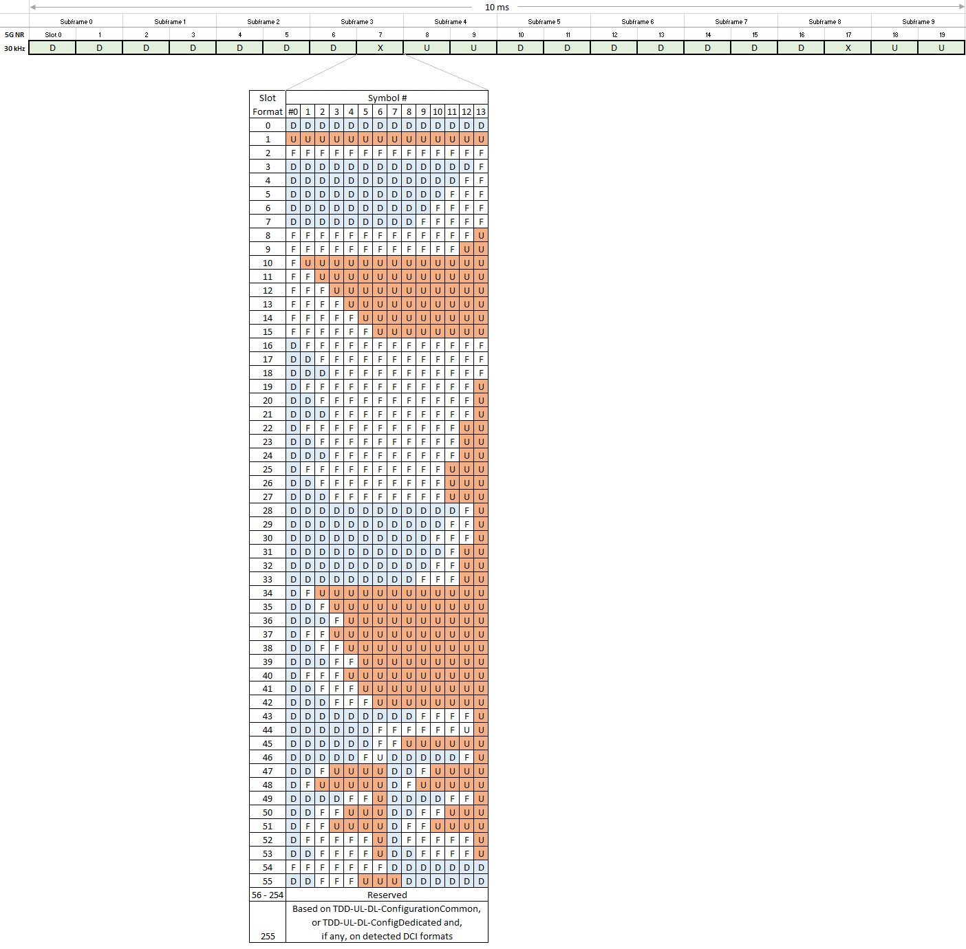
Here is an example log for TDD slot allocation.
tdd-UL-DL-ConfigurationCommon
referenceSubcarrierSpacing --- kHz30(1)
dl-UL-TransmissionPeriodicity --- ms5(6)
nrofDownlinkSlots --- 0x7(7)
nrofDownlinkSymbols --- 0x8(8)
nrofUplinkSlots --- 0x2(2)
nrofUplinkSymbols --- 0x4(4)
This would mean sequential 7 DL slots and, 8 DL symbols + 2 Flexible symbols + 4 UL symbols on the mixed slot, and then sequential 2 UL slots. It can be illustrated below.

The slot format with symbols for the mixed slot would be configured with signalling (tdd-UL-DL-ConfigurationCommon or/and tdd-UL-DL-ConfigurationDedicated) or DCI without signalling. Here is the whole slot format table below, which comes from TS 38.213 Table 11.1.1-1.
# Reference
- TS 38.213 Physical layer procedure for control
- TS 38.101-1 User Equipment (UE) radio transmission and reception - Part 1: Range 1 Standalone
- TS 38.101-2 User Equipment (UE) radio transmission and reception - Part 2: Range 2 Standalone