Pages

5G NR Architecture Deployment Options

Whenever you are facing with 5G New Radio deployment, you would hear there are several options. Some would call it RAN architecture. We are going to walk through what options are available and how to understand them in terms of specifications.

Mapping Architecture Options to Dual Connectivity Variants


First of all these options are not official 3GPP specifications terminology, but they were proposed in Technical Reports based on 5G architecture study; TR 38.801 and TR 38.804. If you go through these options, we would be able to map them to Dual Connectivity, which is described in TS 37.340. These families would be called as Non-Standalone (NSA).
  • Option 3 (3/3a/3x) family or EN-DC (E-UTRA - New Radio Dual Connectivity): eNB works as Master (MeNB) and gNB works as Secondary (SgNB), and both are connected to EPC
  • Option 7 (7/7a/7x) family or NGEN-DC (Next Generation E-UTRA - New Radio Dual Connectivity): eNB works as Master (MeNB) and gNB works as Secondary (SgNB), and both are connected to 5G Core
  • Option 4 (4/4a) family or NE-DC (NG-RAN - E-UTRA Dual Connectivity): gNB works as Master (MgNB) and eNB works as Secondary (SeNB), and both are connected to EPC
Obviously these 3 option families above are the most hottest topic and there are more options like below; totally 8.
  • Option 1: eNB works with EPC (So called legacy LTE architecture.)
  • Option 2 or Standalone (SA) NR: gNB works with 5GC (Final stage along with the migration route.)
  • Option 5 or Standalone (SA) eLTE: eNB works with 5GC (Does it make sense? It would be feasible once 5GC is deployed in the end.)
  • Option 6: gNB works with EPC (Does it make sense? It has not been finalized in specifications.)
  • Option 8 family: gNB works as Master (MgNB) and eNB works as Secondary (SeNB), and both are connected EPC (Who might use this? It has not been finalized in specifications.)

Option 3 (3/3a/3x) family


Then let's go through option 3 family, which has sub-options, so called 3, 3a, 3x. The main differences are how to transmit user plane connectivity between Radio Access Network and Core Network. We can find a bunch of explanation on TR 38.801 and TR 38.804. 

Split bearer concept has been introduced in Dual Connectivity at TS 37.340. For control plane, EPC is going through MeNB to the UE. For user plane, big difference between 3/3x and 3a is X1-U interface between MeNB and SgNB (3/3x) or none (3a).

Option 3 is defined to use an MCG split bearer, which would require more process (investment) on the current eNB side. I am not sure how much operators would like to do with this. Option 3a is done to use a perfect Split bearer, which let operators invest on the gNB that they are going to deploy. Then option 3x is combined and modified practically to use an SCG slit bearer, which let operators save budgets on the eNB side and have benefit in utilizing the user plane through both MeNB and SgNB.

Here is the summary on option 3 family below based on TR 38.801 and TR 38.804.


( : eNB,: gNB,: EPC,: 5GC, click to zoom this)

Option 3x would be the prevalent one among operators who would initiate 5G services. It allows them save budget on eNB side and invest on gNB, and then utilize the 5G user plane via both eNB and gNB. If 3x is deployed, option 7x below would be the next step they would go to. Then they would go to option 4 family or 2 directly. However some operator would like to jump on option 2 by skipping all these Dual Connectivity step stones.

Option 7 (7/7a/7x) family


With option 7 (7/7a/7x) family, the same Radio Access Network itself is not changed from option 3 family, but RAN is connected to 5G Core Network instead. In order to differentiate option 7 family from others, it is called NGEN-DC (NG-RAN E-UTRA NR - Dual Connectivity).

Here is the summary on option 7 family based on TR 38.801 and TR 38.804. (click to zoom this)


Option 4 (4/4a) family


Once 5G Core Network is deployed and work with NG-RAN, the next step would be option 4 family or option 2. I am not sure how practically useful option 4 family. Anyways here is the summary on option 4 family based on TR 38.801 and TR 38.804. (click to zoom this)


# References


5G NR Frame structure and Slot configuration

Unlike LTE, there are multiple options available in order to cover various scenarios like eMBB, URLLC, or mMTC.

Frame structure with Numerologies


10 subframes (= 20 slots) are fit into 10 ms in LTE while various number of slots depending on Numerology are fit into 10 ms in 5G NR. Yes it brought multiple options in sub-carrier spacing, which is called as Numerologies; 15 through 240 kHz. Let me illustrate New Radio frame structures with multiple SCS below.


It is hard to see this type of illustration because there are multiple sub-carrier spacing and it is barely provided as a picture. I was able to draw this above as putting pieces together; TS 38.211 Table 4.2-1 and Table 4.3.2-1. Both table would be combined into one with my understanding here.


For your reference, let's compare the LTE frame and 5G NR's with 15 kHz. As long as you would see both subframe and slot at the same time, you would get confused. LTE resource would be allocated every subframe base while NR's would be done every slot base.


Slot configuration with Numerologies


As you can see, 14 symbols would be stuffed in a single subframe (= 2 slots = 1 ms) in LTE while the same number of symbols would be fit into a single slot (= 1 subframe = 1 ms) in NR with 15 kHz SCS. In LTE, 14 symbols would be fit into a single subframe, which is always 1 ms. In NR, 14 symbols would be done into a single slot, which varies per subcarrier spacing. Since the absolute slot size (length) are defined differently as SCS, it seems quite confusing to us. 

As you can see, 15 through 240 kHz sub-carrier spacing are defined in TS 38.211 Table 4.2-1. The frame structures are defined in TS 38.211 Table 4.3.2-1. Both table would be combined into one with my understanding here. 


If we compare the top 4 SCS slot configuration, it can be illustrated below. The same number of symbols would be delivered in different time slot and frequency spans below. A larger monitor would give you this real big picture.


Slot format - stuffing with symbols


In 5G NR, we would have to differentiate paired frequency and duplex time. If paired frequency bands are used, full duplex (FDD - Frequency Duplex Division) can be used simply. If unpaired one is used, time duplex (TDD - Time Duplex Division) should be used. Especially 5G NR would call it dynamic TDD.

There are a few different subframe configuration in LTE, which is not available any more in 5G NR. So the configuration based on Slot would be broadcast from SIB1 or/and configured with RRC Connection Reconfiguration message.

Here is an example log for TDD slot allocation.

tdd-UL-DL-ConfigurationCommon
  referenceSubcarrierSpacing --- kHz30(1)
  dl-UL-TransmissionPeriodicity --- ms5(6)
  nrofDownlinkSlots --- 0x7(7)
  nrofDownlinkSymbols --- 0x8(8)
  nrofUplinkSlots --- 0x2(2)
  nrofUplinkSymbols --- 0x4(4)

This would mean sequential 7 DL slots and, 8 DL symbols + 2 Flexible symbols + 4 UL symbols on the mixed slot, and then sequential 2 UL slots. It can be illustrated below.


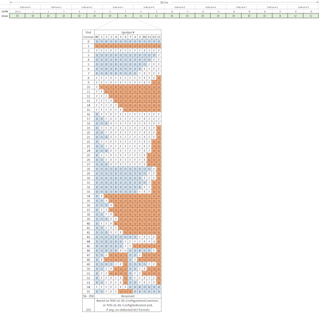
The slot format with symbols for the mixed slot would be configured with signalling (tdd-UL-DL-ConfigurationCommon or/and tdd-UL-DL-ConfigurationDedicated) or DCI without signalling. Here is the whole slot format table below, which comes from TS 38.213 Table 11.1.1-1.


# Reference

  • TS 38.213 Physical layer procedure for control
  • TS 38.101-1 User Equipment (UE) radio transmission and reception - Part 1: Range 1 Standalone
  • TS 38.101-2 User Equipment (UE) radio transmission and reception - Part 2: Range 2 Standalone

5G NR fundamental terms

Let's go over new terms with 5G NR assuming you are familiar with 4G or LTE.


  • 5G: The 5th generation cellular communications. 
  • 5G NR: 5G New Radio.
  • 5GC: 5G Core Network.
  • 5QI: 5G QoS Identifier, which can be allocated to a QoS Flow.
  • AMF: Access and Mobility Management Function - It handles NAS communications and mobility. 
  • ARP: Allocation and Retention Priority - NG-RAN can allocate its resources relatively per QoS flow compared to others by using Allocation and Retention Priority IE. 
  • BA: Bandwidth Adaptation - BWP (Bandwidth Parts) is a subset of channel bandwidth and Bandwidth Adaptation would be done by configuring the UE with BWP(s) and telling the UE which of the configured BWPs is currently the active one.  
  • BWP: Bandwidth Parts - It is a subset bandwidth of the total cell bandwidth of a cell. 
  • CFRA: Contention Free Random Access - Random Access procedure when a dedicated resource is decided. It would be used for adding PSCell to PCell. 
  • CORESET: Control Resource Set.


TS 38.300 Figure 4.1-1 Overall Architecture

  • en-gNB: Variant Next Generation Node B - Node provides NR user plane and control plane protocol to the UE. It would act as Secondary Node in EN-DC. 
  • EN-DC: EUTRA-NG Dual Connectivity - It would work with eNB as a Master Node and (en-)gNB as a Secondary. This term is officially used in 3GPP Technical Specifications replacing deployment option 3 family (3/3a/3x) 3GPP Technical Report. 
  • gNB: Next Generation Node B - Node provides NR user plane and control plane protocol to the UE, and connected via the NG interface to 5GC. It would act as Secondary Node in NGEN-DC. 
  • I-RNTI: Inactive RNTI.
  • INT-RNTI: Interruption RNTI.
  • LDPC: Low Density Parity Check - It would be used to decode NR PDSCH. 
  • MCG: Master Cell Group in MR-DC - A group of serving cells associated with the Master Node (PCell - Primary Cell) and optionally one or more SCells. 
  • MN: Master Node - Radio access node to provide the control connection to the core network. It can be a MeNB (Master eNB) in EN-DC, a Mng-eNB (Master ng-eNB) in NGEN-DC, or a MgNB (Master gNB) in NE-DC or NR-DC. 
  • MICO: Mobile Initiated Connection Only.
  • MFBR: Maximum Flow Bit Rate.
  • MR-DC: Multi-Radio Dual Connectivity - Dual Connectivity between E-UTRA and NR nodes, or between two NR nodes. 
  • NCGI: NR Cell Global Identifier. 
  • NE-DC: Next Generation EUTRA Dual Connectivity. This term is officially used in 3GPP Technical Specifications replacing deployment option 4 family (4/4a) 3GPP Technical Report. 
  • NGEN-DC: NG Core compatible EN-DC - It would work with ng-eNB as a Master Node and gNB as a Secondary. This term is officially used in 3GPP Technical Specifications replacing deployment option 7 family (7/7a/7x) 3GPP Technical Report. 
  • ng-eNB: NG interface connected eNB - Node provides LTE user plane and control plane protocol to the UE, and connected via the NG interface to 5GC. It would act as Master Node in EN-DC, or Secondary in NE-DC.
  • NG Interface: Interface between gNB and 5GC. 
  • NG-RAN: Either a gNB or an ng-eNB.
  • NR: New Radio Access for 5G.
  • Numerology: One subcarrier spacing in the frequency domain. 
  • Deployment Options: Various different network deployment options were proposed in 3GPP Technical Report. The most smooth deployment path is going to be Option 3 family (3/3a/3x), and it goes to option 7 (7/7a/7x), and then it goes to option 4 (4/4a). 
  • PCell: SpCell of a master cell group.
  • PSCell: SpCell of a secondary cell group.
  • QFI: QoS Flow ID, which is marked with a 5QI. 
  • RANAC: RAN-based Notification Area Code.
  • RMSI: Remaining Minimum System Information.
  • RNA: RAN-based Notification Area.
  • RNAU: RAN-based Notification Area Update.
  • SD: Slice Differentiator.
  • SFI-RNTI: Slot Format Indication RNTI.
  • SCG: Secondary Cell Group in MR-DC - A group of serving cells associated with the Secondary Node (PSCell - Primary Secondary Cell) and optionally one or more SCells. 
  • Slot Format: Symbol DL/UL structure based on a Slot for NR.
  • SMF: Session Management Function.
  • S-NSSAI: Single Network Slice Selection Assistance Information.
  • SpCell: Primary cell of a master or secondary cell group.
  • Split bearer: A radio bearer with RLC bearers both in MCG and SCG, which share the same PDCP in common. 
  • Split SRB: A SRB between the MN and the UE with RLC bearers both in MCG and SCG, which share the same PDCP in common. 
  • SRB3: A direct SRB between the SN and the UE in EN-DC, NGEN-DC, and NR-DC. 
  • SUL: Supplementary Uplink - Uplink only frequency band defined for 5G. 
  • UPF: User Plane Function.
  • URLLC: Ultra-Reliable and Low Latency Communications.
  • Xn: Interface among gNBs.

# References

  • TS 38.300 NR and NG-RAN Overall Description
  • TS 38.413 Physical layer procedures for control - 8.2.1 PDU Session Resource Setup
  • TS 38.213 Physical layer procedures for control - 11.1.1 UE procedure for determining slot format