Mapping Architecture Options to Dual Connectivity Variants
First of all these options are not official 3GPP specifications terminology, but they were proposed in Technical Reports based on 5G architecture study; TR 38.801 and TR 38.804. If you go through these options, we would be able to map them to Dual Connectivity, which is described in TS 37.340. These families would be called as Non-Standalone (NSA).
- Option 3 (3/3a/3x) family or EN-DC (E-UTRA - New Radio Dual Connectivity): eNB works as Master (MeNB) and gNB works as Secondary (SgNB), and both are connected to EPC
- Option 7 (7/7a/7x) family or NGEN-DC (Next Generation E-UTRA - New Radio Dual Connectivity): eNB works as Master (MeNB) and gNB works as Secondary (SgNB), and both are connected to 5G Core
- Option 4 (4/4a) family or NE-DC (NG-RAN - E-UTRA Dual Connectivity): gNB works as Master (MgNB) and eNB works as Secondary (SeNB), and both are connected to EPC
- Option 1: eNB works with EPC (So called legacy LTE architecture.)
- Option 2 or Standalone (SA) NR: gNB works with 5GC (Final stage along with the migration route.)
- Option 5 or Standalone (SA) eLTE: eNB works with 5GC (Does it make sense? It would be feasible once 5GC is deployed in the end.)
Option 6: gNB works with EPC (Does it make sense? It has not been finalized in specifications.)
Option 8 family: gNB works as Master (MgNB) and eNB works as Secondary (SeNB), and both are connected EPC (Who might use this? It has not been finalized in specifications.)
Option 3 (3/3a/3x) family
Then let's go through option 3 family, which has sub-options, so called 3, 3a, 3x. The main differences are how to transmit user plane connectivity between Radio Access Network and Core Network. We can find a bunch of explanation on TR 38.801 and TR 38.804.
Split bearer concept has been introduced in Dual Connectivity at TS 37.340. For control plane, EPC is going through MeNB to the UE. For user plane, big difference between 3/3x and 3a is X1-U interface between MeNB and SgNB (3/3x) or none (3a).
Option 3 is defined to use an MCG split bearer, which would require more process (investment) on the current eNB side. I am not sure how much operators would like to do with this. Option 3a is done to use a perfect Split bearer, which let operators invest on the gNB that they are going to deploy. Then option 3x is combined and modified practically to use an SCG slit bearer, which let operators save budgets on the eNB side and have benefit in utilizing the user plane through both MeNB and SgNB.
Here is the summary on option 3 family below based on TR 38.801 and TR 38.804.

(
 : eNB,
 : gNB,
 : EPC,
 : 5GC, click to zoom this)
Option 3x would be the prevalent one among operators who would initiate 5G services. It allows them save budget on eNB side and invest on gNB, and then utilize the 5G user plane via both eNB and gNB. If 3x is deployed, option 7x below would be the next step they would go to. Then they would go to option 4 family or 2 directly. However some operator would like to jump on option 2 by skipping all these Dual Connectivity step stones.
Option 7 (7/7a/7x) family
With option 7 (7/7a/7x) family, the same Radio Access Network itself is not changed from option 3 family, but RAN is connected to 5G Core Network instead. In order to differentiate option 7 family from others, it is called NGEN-DC (NG-RAN E-UTRA NR - Dual Connectivity).
Here is the summary on option 7 family based on TR 38.801 and TR 38.804. (click to zoom this)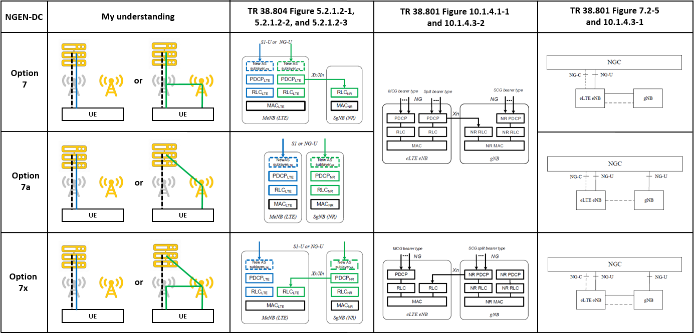
Option 4 (4/4a) family

# References
- TS 37.340 Multi-connectivity - Overall description
- TR 38.801 Radio access architecture and interfaces
- TR 38.804 Radio interface protocol aspects
- Wireless Technology Evolution - Transition from 4G to 5G (5G Americas)
- 5G New Radio - A New Era for Enhanced Mobile Broadband (Mediatek)